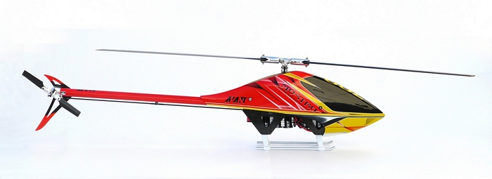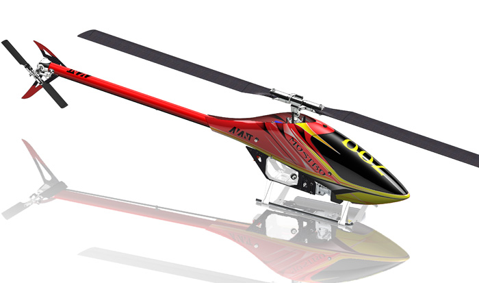
Mostro ElectriC 700 MANUAL
Products
Avant RC manufactures Radio Control Helicopter kits. They are divided in the Mostro Branch, the Aurora branch and the FX and EFX conversion kits. Among the Mostro branch and the Aurora branch there are the Nitro and Electric versions of each one.
Mostro 700 Nitro Released
Mostro 700 Nitro Released
We’re happy to announce that the Mostro 700 Nitro has been released.
This is the most advanced Nitro in the Market and it’s the only one that incorporates the latest design techniques into a Nitro model.
Nitro pilots no longer need to feel left out of the new wave of RC Helicopter design because they now have not just a new Nitro but the most advanced Nitro ever built available.
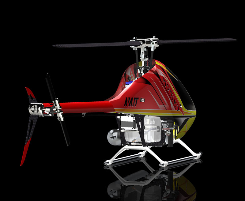
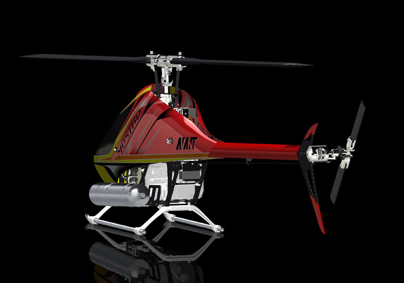
Mostro Nitro Modern Design
The Mostro 700 Nitro. The first Modern Design Nitro in the market.
The Mostro 700 Nitro is the first Modern nitro in the market that has all the modern design features normally found only in advanced electrics like the Mostro 700 electric.
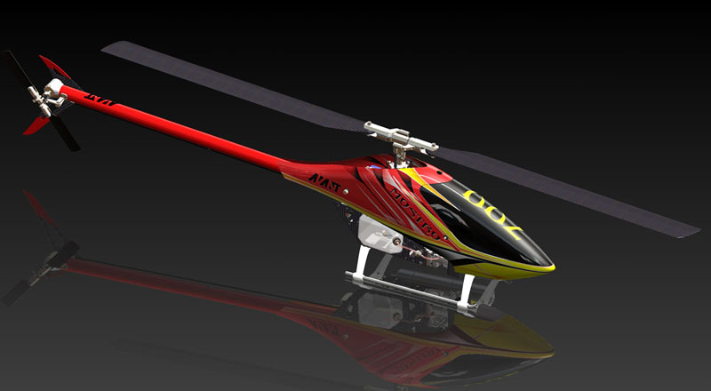
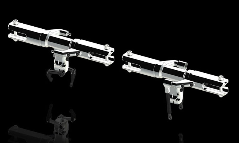
The Mostro Nitro is available with both DFC or FA (Follower Arms) heads. Both heads feature the famous RigidCore dampening system.
A dampening system that allows rigidity to work at all head speeds including very low ones.
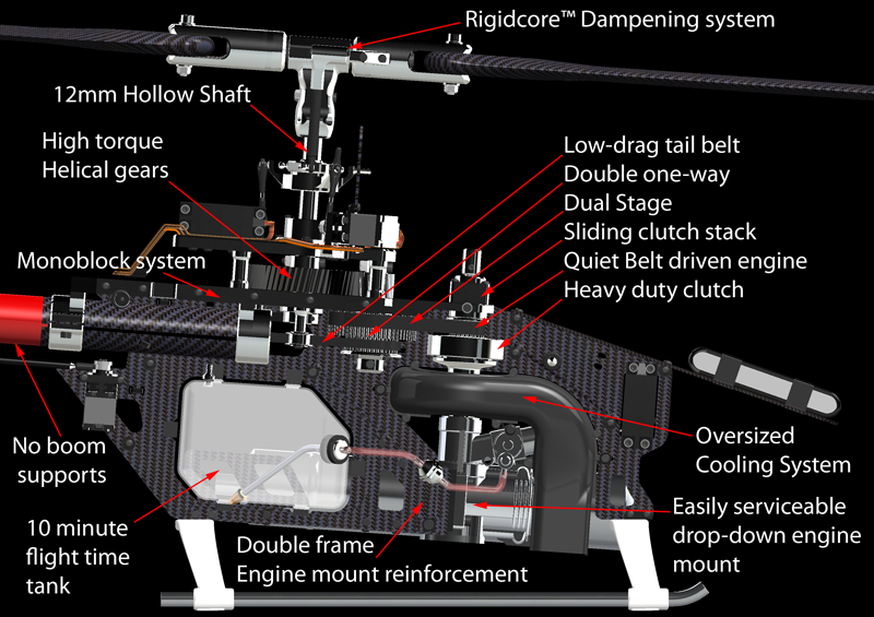
Features always wanted by Nitro pilots and enjoyed by electric pilots are now available in the Mostro Nitro.
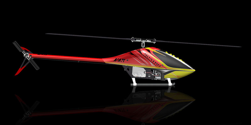
A beautiful and sexy design makes the Mostro an attractive model that will turn heads at the flying field.
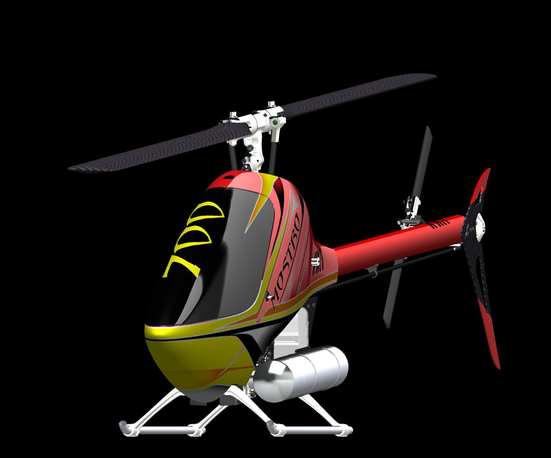
Sexy!
The Mostro Monoblock
This is truly a new approach that we are introducing in the market.
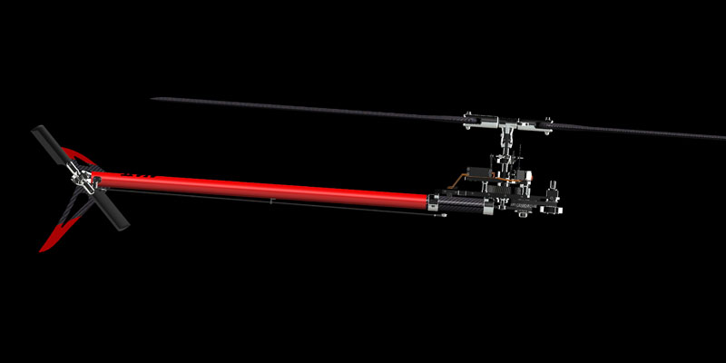
When designing the Mostro, we wanted to have all the mechanics connected rigidly, without flexible elements unless dampening is required. The result was the design of what we call the Mostro “Monoblock” ( single block).
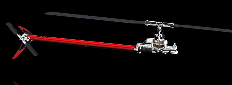
In the Monoblock design, all elements of the system that affect the gyro sensing are mounted in a rigid superstructure. No part rests on the flexible frames unless it needs dampening.
The Monoblock is actually the flying helicopter.
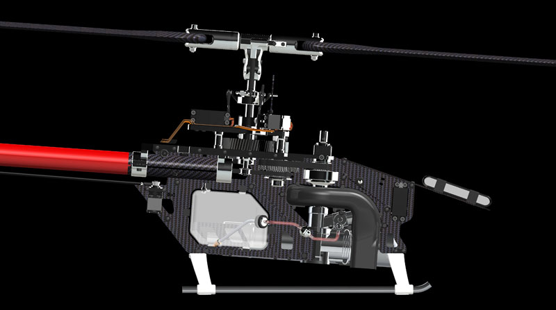
Everything in the Mostro nitro is readily and easily accessible. Repairs are a breeze and easy access to the engine is unparalleled.
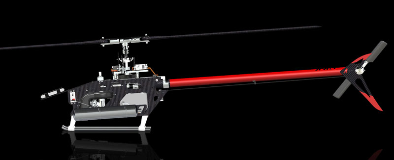
No boom supports needed.
Boom supports are a thing of the past. The machines need to look nicer. The technology is available so why not use it? Yes the obvious answer is Carbon Fiber. The lightness and extreme rigidity of the boom made out of carbon can only be enhanced when a much larger diameter boom is used. Also why round? Because round is the ideal cross-section to handle torque.
It is not only the shape of the boom that is important, but also how it is supported. In the Mostro we have two far away spaced boom clamps that decrease the bending force applied to the boom.
We also made the area of physical contact between the clamp and the boom very large so that the clamp pressure is spread across a larger area, protecting the tube from damage due to excessive tightening.
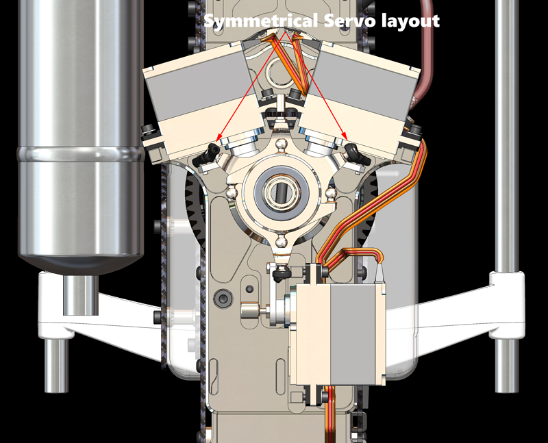
Servo layout because symmetry matters…
We wanted to have the shortest possible distance between the swashplate and servos without resorting to weird geometries, that forces the electronic FBL unit to fight back geometry that is not best suited to mimic what the radio control system’s gimbal does.
No matter what system you are using, the radio’s gimbal is composed of two potentiometers that measure two angles. Those angles are the horizontal and the vertical movements of the stick by your finger.
The best way to match that is to have symmetry in those two directions. The most critical direction in manoeuvres is the side to side movement, which is naturally better driven via two “mirror-image” configuration servos, so that manoeuvres like fast aileron tic-tocs are performed mostly by the mechanics and less by the electronics trying to compensate for the mechanics weird geometry. This results in a lessened delay between the FBL gyro sensors detection of an unintended movement created by odd geometry, and also a lessening of the correction that it has to do to compensate.
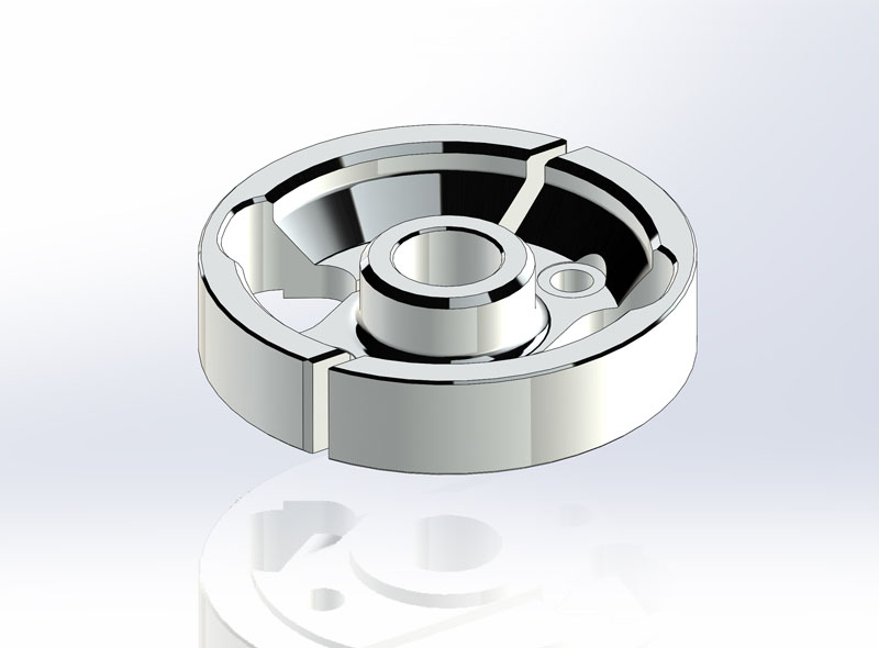
Rugged clutch sized for today’s 120 sized engines. No slipping or breaking due to our exclusive no-fatigue shoe spring design.
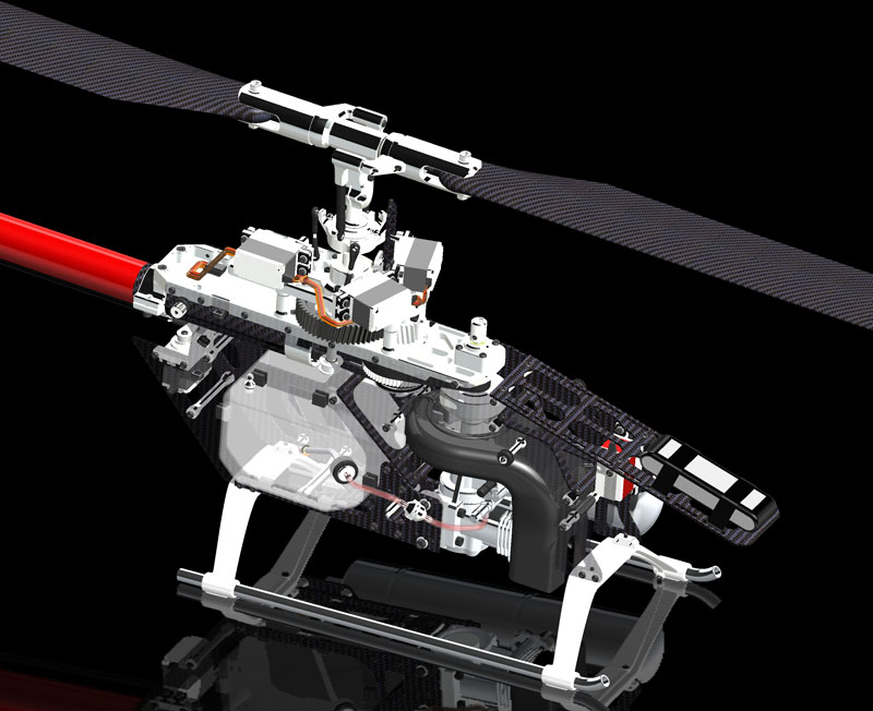
Very high frame rigidity is achieved with lightweight carbon frame stiffeners elements.
Really large volume of air cooling system allows leaner engine settings delivering more power than other systems.
Get your Nitro today by clicking here.
New Top Servo Plate for the New Non-Standard Servo Geometries
New Top Servo Plate for the New Non-Standard Servo Geometries
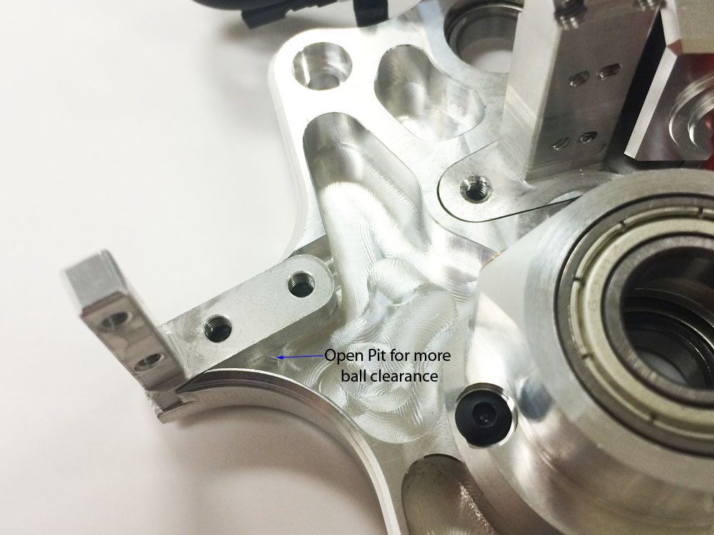
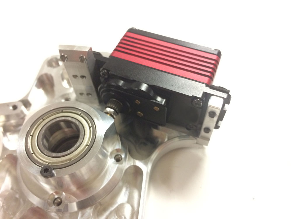
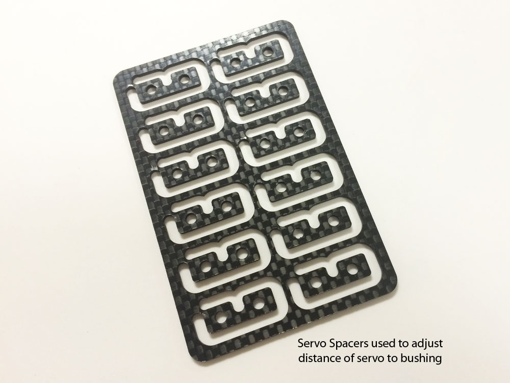
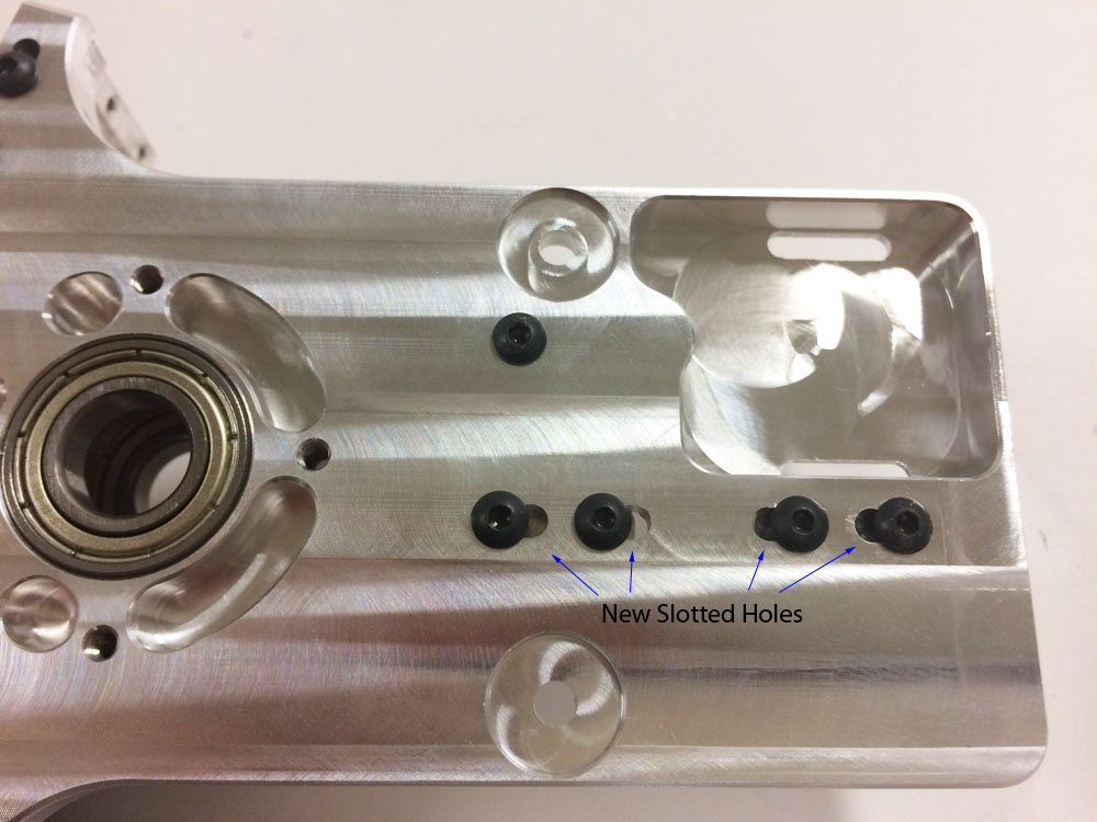
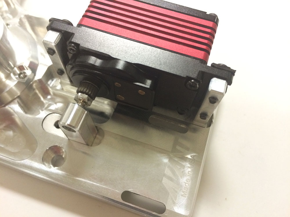
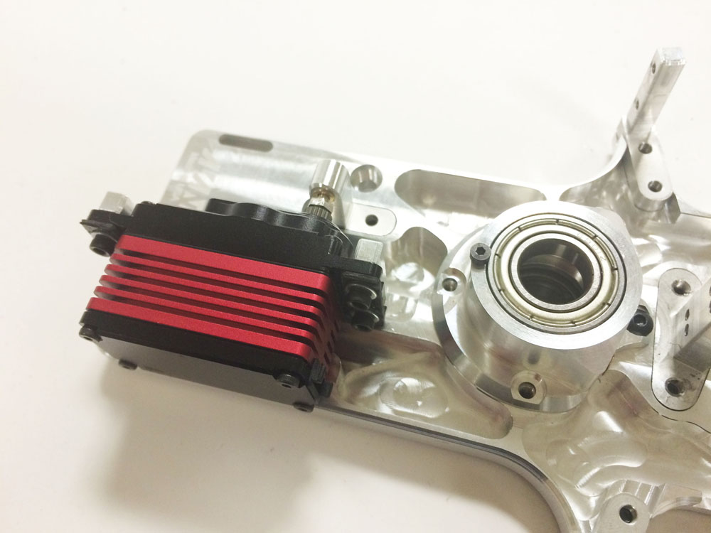
Several manufacturers are coming out with new servos that don’t fit the standard JR and Futaba servo geometry. Due to those new geometries we decided to develop an adjustable geometry top servo plate. The main difference is in that it has the servo posts mounting holes converted to slots for adjustability.
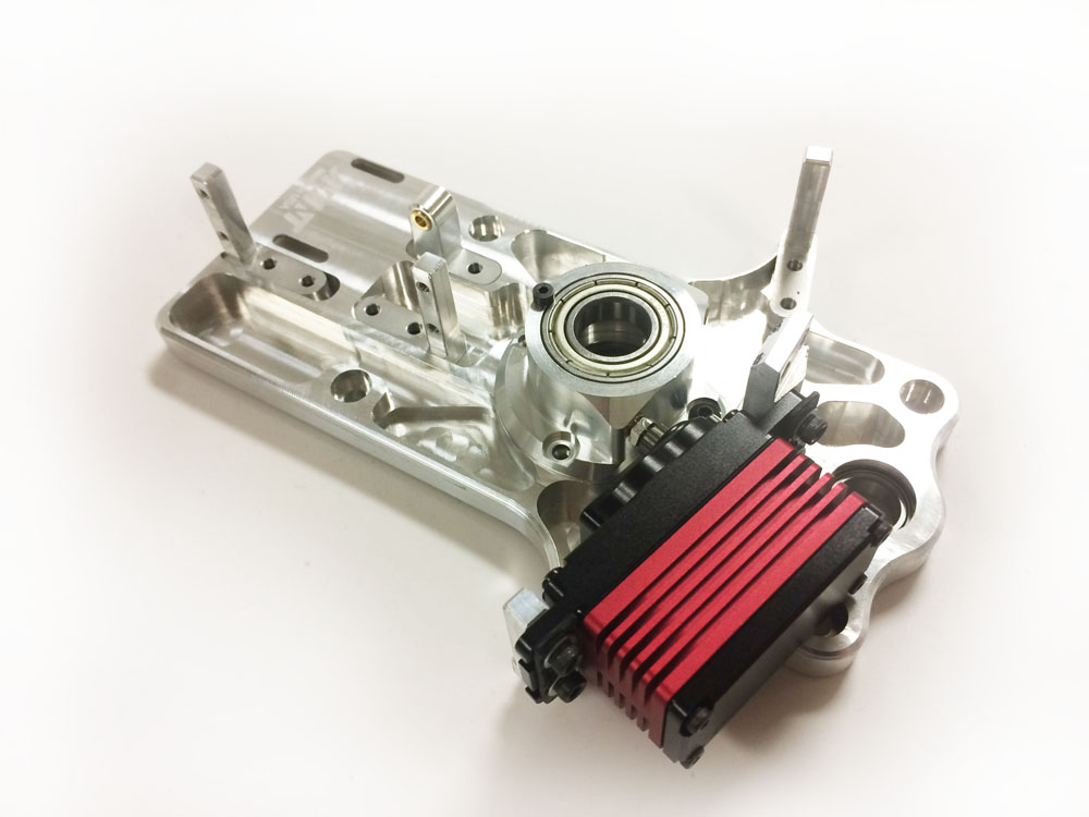
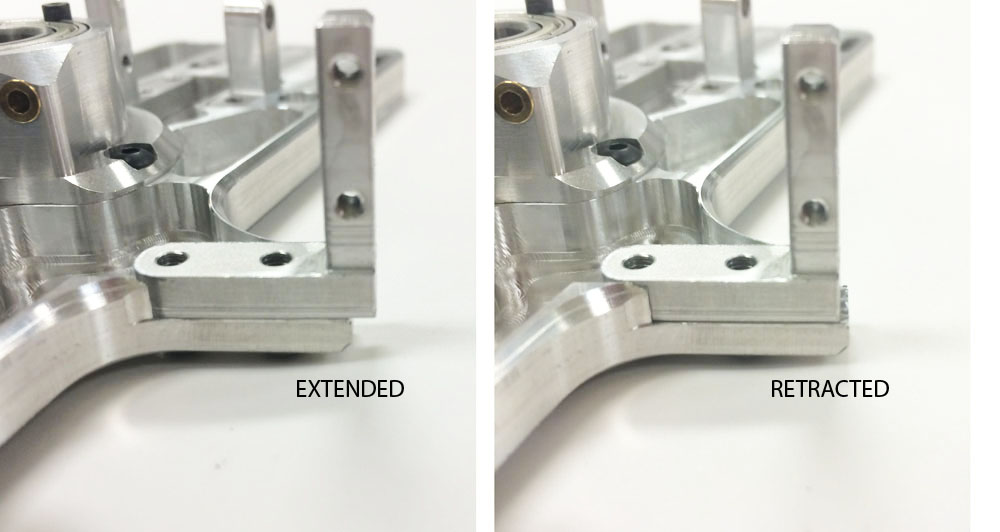
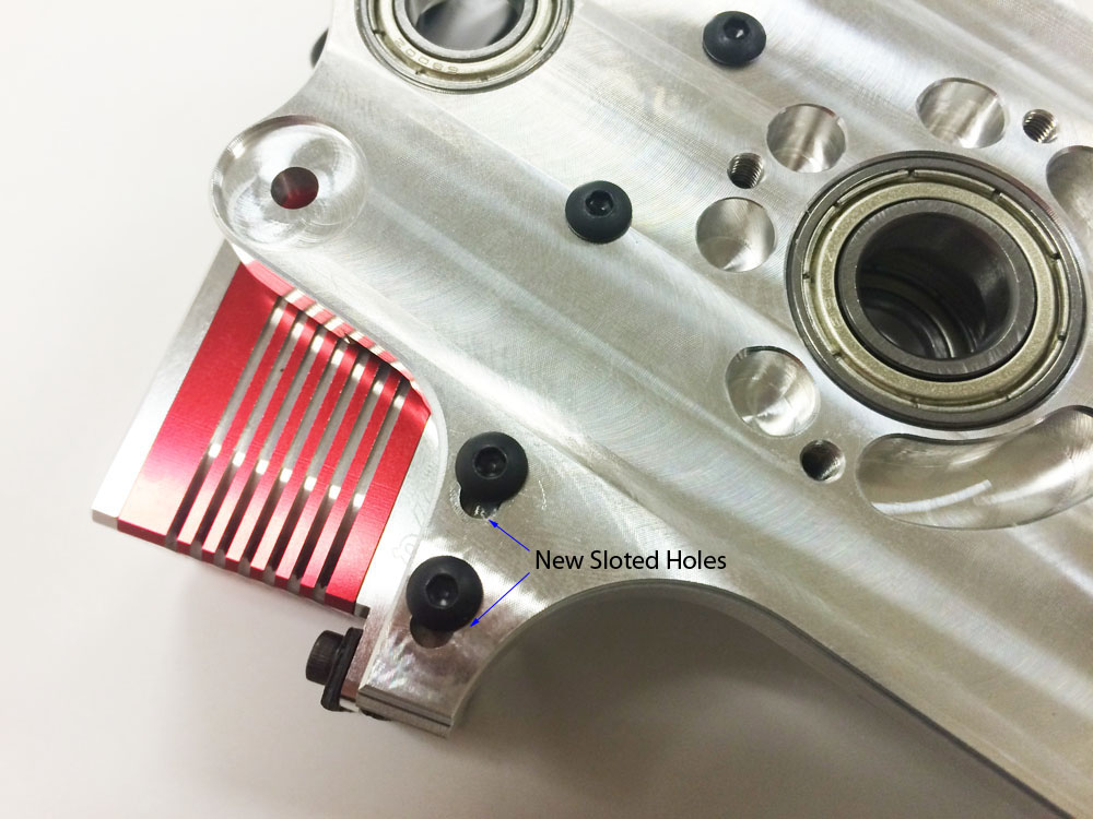
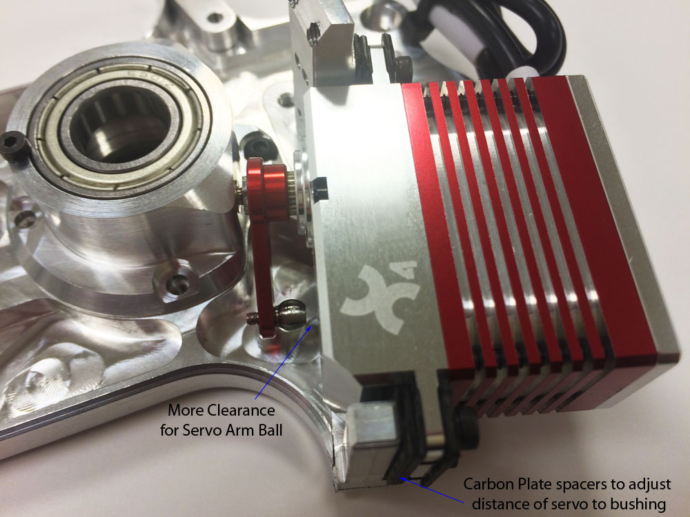
Avant RC.
New wide Landing Gear, Lower stance frame and color schemes
Based on customer’s feedback we decided to make a new landing gear mold to widen the landing gear. The part will be shipping the week after next and will be available as an spare part and in future kits. Notice also that we made a new version of the frames for an even lower profile. The Landing gear now partially hides inside the canopy. The lower stance frame is a drop-in replacement for the original one and is currently shipping as the standard kit frame in all kits.
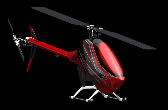
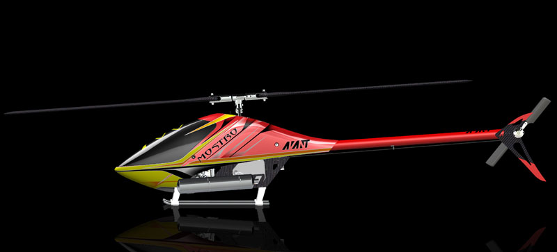
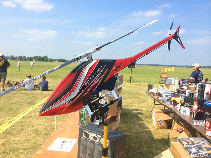
This is the red version of a new color scheme available as an optional set. There is also a neon yellow version pictured below. This version is being previewed in the new Mostro Nitro introduced at the IRCHA 2014 event.
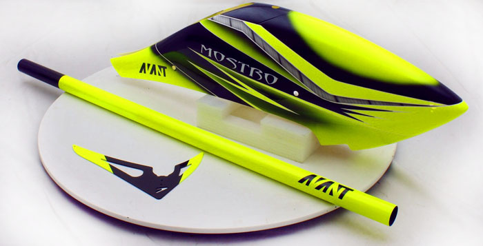
The new color schemes will be available as optional parts. Kits will ship with the original canopies. The red scheme uses the same red boom and fin used in the original kit so only the canopy is different.
Mostro Design Insights – Correct Servo linkage geometry design
We have had several people ask us why the servo rods have a slight angle of inclination when at zero degrees pitch. Not knowing any better and seeing other incorrect designs where the linkage rods are perfectly vertical they wonder if there is a mistake in their setups.
We sometimes forget that not everyone is so into perfection and attention to detail so they might not be aware of the level of attention we place on even the slightest details.
Mostro Design Insights – Correct Servo linkage geometry design.
When doing servo linkage geometry you need to take into consideration that the servos are rotating arms and not linear actuators. That being said it’s an inherent part of a rotating actuator device to have a component of travel that’s undesired and perpendicular to the travel of interest. This shift is usually called interaction error.
When designing the geometry one needs to take into account that interaction and try to minimize the effects of it during flight so that the electronics don’t have to work so hard to compensate for mechanical errors. It also help them in the PID engine algorithm calculations so that the deviations from the expected feedback are minimized and less correction is required.
We understand that from a marketing point of view a perfectly vertical linkage rod at zero degrees collective pitch looks very pretty but we are too much of perfectionist hardcore engineers to let marketing dictate the correct functioning of the mechanics instead of math.
To illustrate a simplified view of what we’re referring to please take a look at the following pictures.
CORRECT DESIGN:
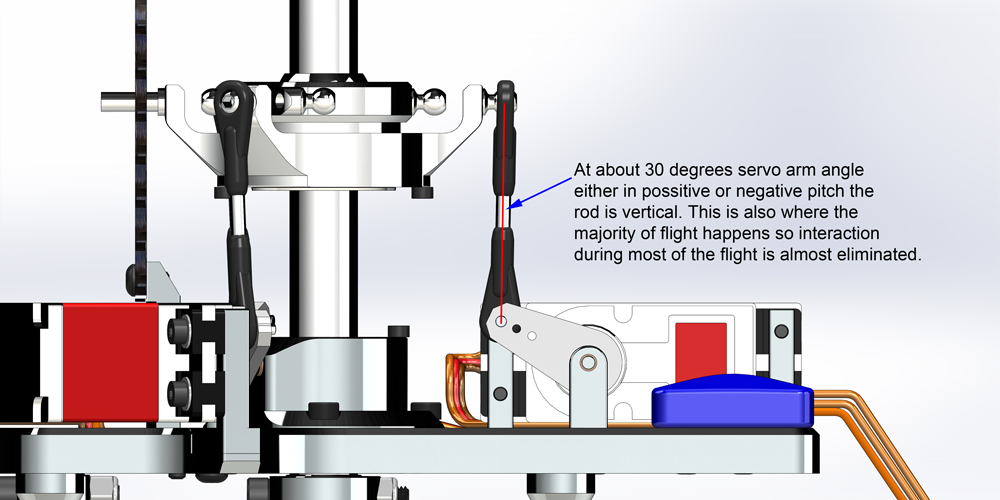
In the first picture we can see how the Mostro’s swashplate to servo linkage rod is slightly shifted forward creating a slight angle when compared to a vertical line. This is done on purpose to minimize the effects of interaction.
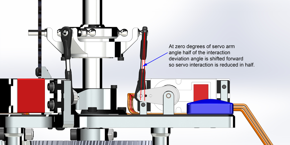
As you can see in the next picture at a slight positive or negative pitch the link is vertical. This is where most of the flying happens because when your helicopter is flying it needs either a positive or negative pitch angle to generate lift and prevent it from falling. This is where you need to try to have the minimum amount of interaction and it’s why at this point it’s vertical.
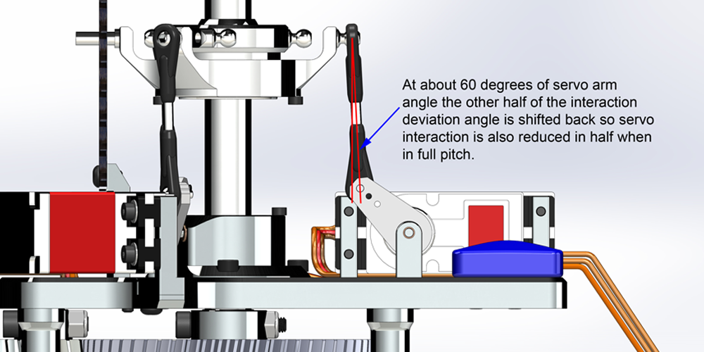
In the next picture you can see that at full pitch the interaction angle now goes the opposite way and it’s half of the total angle cutting in half the potential interaction at full pitch travel.
INCORRECT DESIGN:
Compare this to a poorly designed geometry. In this case the rods are vertically aligned and we agree that it looks really pretty because it seems nice and aligned but that where the pretty stops because when full pitch is applied the error from interaction is doubled due to the unnecessarily excessive angle that the fbl system needs to fight against.
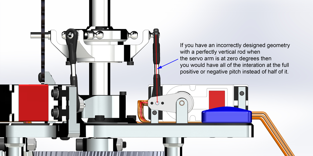
You can see in this picture how a poorly designed geometry can increase the interaction error to double what it could be.
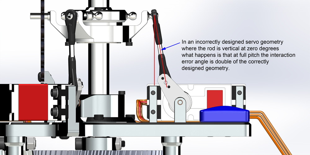
It’s this attention to details that make the Mostro such an amazingly awesome flying machine. You wouldn’t think that this level of attention to details is important but when to many are done in a machine design the result is a superbly flying machine. We will continue with a series of articles about design insights on the Mostro.
Hope this helps people understand how the interaction can be minimized with a properly designed geometry.
Avant RC.
Mostro 700 electric gear ratios
Servo arm spacing is 17mm. Most people are using the secraft’s aluminum arms that break in case of a crash.
The stock ratio is:
First pulley 20T, optional 21T, 22T and 23T
Second pulley: 61T
Third Pinion: 17T
Fourth Main Gear: 58T
Ratio =(61/first pulley)*(58/17)
Ratios:
20T = 10.406
21T = 9.910
22T = 9.460
23T = 9.048
You can also use a fixed main gear tooth count of 208.12 and use the standard pulley tooth count.
20 : 208.12
21 : 208.12
22 : 208.12
23 : 208.12
Because:
208.12 / 20 = 10.406
208.12 / 21 = 9.910
208.12 / 22 = 9.460
208.12 / 23 = 9.049
Avant RC.

